
Creating Modular Environments
INTRODUCTION
This tutorial is a result of the knowledge acquired during the production of Zest Foundation. That environment started as a simple and casual study of modular sci-fi pieces and quickly grew into one of my biggest personal projects so far.
I learned a lot during the production and I thought I could repay the community with some of this knowledge.
For this environment I used 3ds max for modeling, Photoshop for texture painting and UDK for rendering. I'll try to keep all concepts pretty universal so other engines or modeling packages users can understand it.
I hope you learn a thing or two and I'm very curious to see what you make with the techniques presented in this tutorial. Send me any WIPS or final shots to mail @ thiagoklafke.com, I'll be very happy to see them!
PLANNING
One of the most important steps when working with modular sets is to invest a lot of time in planning. You should always export your pieces to the editor early on to put simple structures together. This is to check aspects like:
- Ease of use
- Repetition
- Forms and shapes
- Composition
Some pieces look amazing when viewed individually but horrible when tiled. You may also get additional ideas when you actually place the pieces in the level, so never skip this step.
I always tend to work on textures first when creating modular sets. Some people prefer to model the pieces first and texture them later, but that's not the best workflow in my opinion. You will probably need to make changes later on and it gets a lot harder if you take the piece to completion without testing it first.
I always try to have at least a very simple diffuse mockup so I can unwrap my pieces as I model them. This saves a lot of time later on, specially when using geometry-space modifiers, such as Bend and FFD.
STARTING YOUR SET
One of my goals with Zest Foundation was to make a large environment using a small handful of textures. This way it would be easier to keep the overall look of the environment consistent and also to save texture memory and time.
One good idea is to define a list of categories of what you will need early on. Think this step as words (units) that you will later on use to create full sentences (groups of units). The environment itself will be the book comprised of various paragraphs (areas). (I hope that makes sense)
For Zest Foundation I used only 3 categories:
- 4-directionally tiling wall
- Trim
- Floor
Of course I used extra textures here and there but the majority of the set was constructed with those 3 textures.
FOLDER STRUCTURE & NAMING CONVENTIONS
Working in an organized environment is very important for an artist. This is highly personal but my folder structure for this kind of project is usually the following:
- ProjectName/Meshes
Where the actual max or maya files go - ProjectName/Textures
PSDs, TGAs etc.. - ProjectName/ASE
Where I save my meshes in ASE format (which is then imported by UDK - you can also use FBX if you prefer but that usually gives me headaches) - ProjectName/Media
WIP shots to post on forums, etc...
My textures are saved the following way: texturename_map. Example: wall01_d, wall01_n, etc...
Inside UDK I like to use the following structure for my Packages:
- Meshes
- Materials
- Prefabs
- Textures
Anything else like post-process chains can go in the root folder.
USING THE GRID
It's very important to keep the boundaries of the pieces inside the grid, otherwise you will get lots of tiny gaps when tiling them.
My "snap to grid" settings are very simple: Snaps to grid points only. I also like to use power of two dimensions for "Home grid spacing". This makes it easier to increment or decrement the grid steps. Example: If you start with a grid value of 8 you can decrease it to 4, 2, 1. If you start with a grid value of 5 however, you won't get rounded values anymore: 2,5, 1,25, etc... You get the idea.
BOUNDING BOXES & CONTACT POINTS
All pieces' bounding boxes should contain inside the 1x1 piece aspect ratio. Even if you make a 90º curved surface its bounding box should still fit on the 1x1 piece aspect ratio. A good tip is to always use cubes to check if the pieces in fact containing inside the 1x1 aspect ratio.
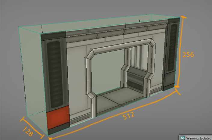
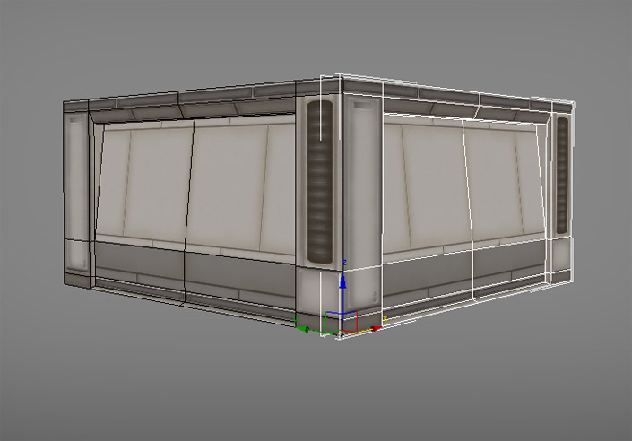
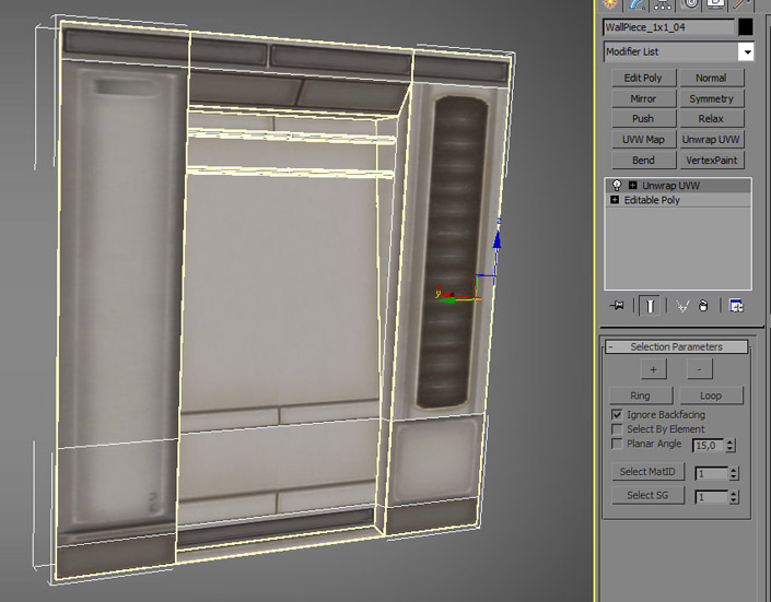
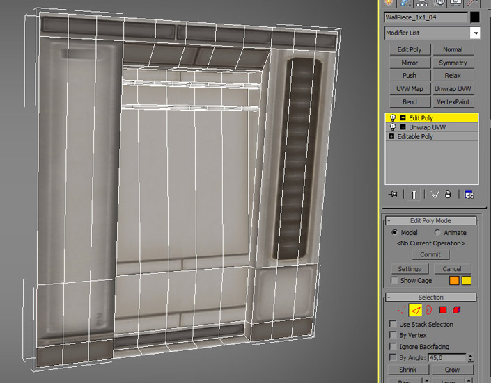
It's not necessary to have X, Y , Z inside the 1x1 aspect ratio. Sometimes only X and Y is fine. This is very true for the wall pieces, which were created out of planes. You are free to do whatever you can inside the plane, but it's a good idea to leave the contact points untouched:
DOWNLOAD THIS SCENE (.max & .obj inside)
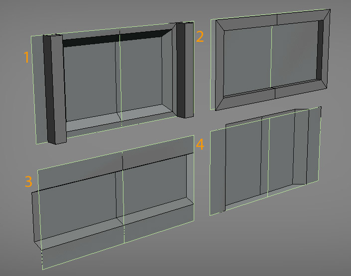
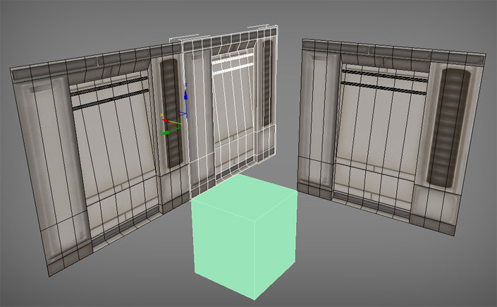
The green plane represents the axis where the pivot is placed.
- Unit 1: Perfect case scenario. All outer edges are in the same plane as the pivot and you won't have any problem combining this with different pieces.
- Unit 2: Worst case scenario. No outer edges are touching the pivot plane. You will only be able to combine this with similar pieces.
- Unit 3: Relatively OK - If you try to combine it with Unit 1 you will have a gap. You will need additional pieces to combine this another units.
- Unit 4: Relatively OK- You will be able to combine this with Unit 1 horizontally, but not vertically. You will also need additional pieces to close the gaps between this piece and the floor and the ceiling.
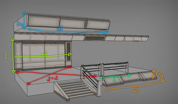
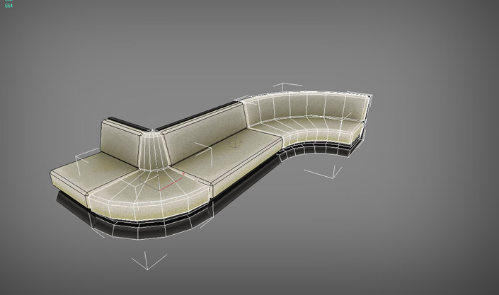
Some of the pieces used in Zest Foundation. The floor piece is actually 2x2. Notice how all other pieces' contact points have square dimensions.
PIVOT PLACEMENT
The Pivot's placement is very important because it will define how easy will be to place your piece in the level. A general rule-of-thumb is to place it in one of the "plane" extremities. Some people prefer to place it on the center of the mesh, but I don't think that's the best approach, because it makes scaling and rotating a little harder.
Example:
Place it on the right spot and it will be a lot easier to rotate and create some interesting combinations:
Tip: When working on a set of walls try to place the pivot in the exact same position for all pieces. This makes it easier to replace units once inside the editor.
(RE)UTILIZING YOUR TEXTURES IN A SMART WAY
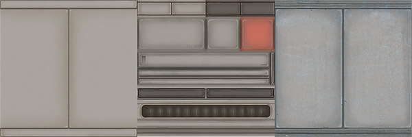
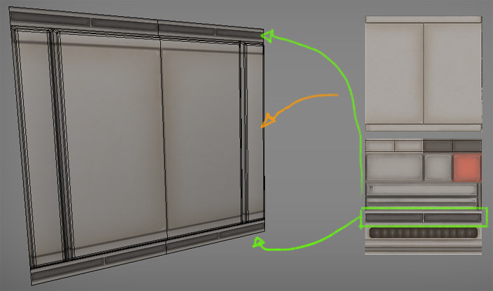
As I said previously, most of the units were created using the same textures. A typical wall unit in Zest Foundation was created out of 2 textures: A 4-directionally tiling texture + a trim texture. I always try to have at least one type of trim when working on textures or units: They help add visual variety and consistency to pieces. You can also do basically anything you want with a good collection of trim textures.
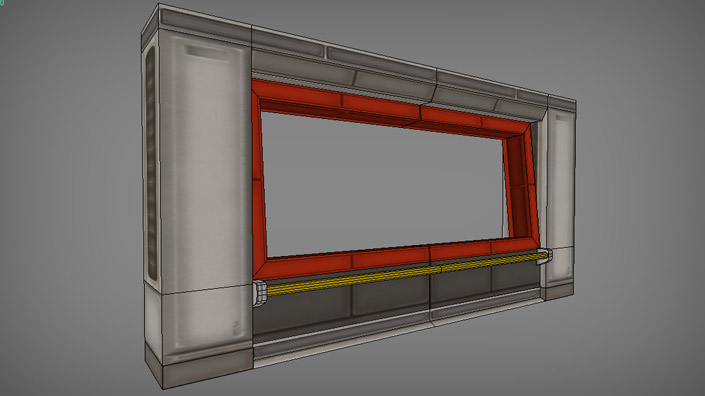
Here's a breakdown of some of the pieces:
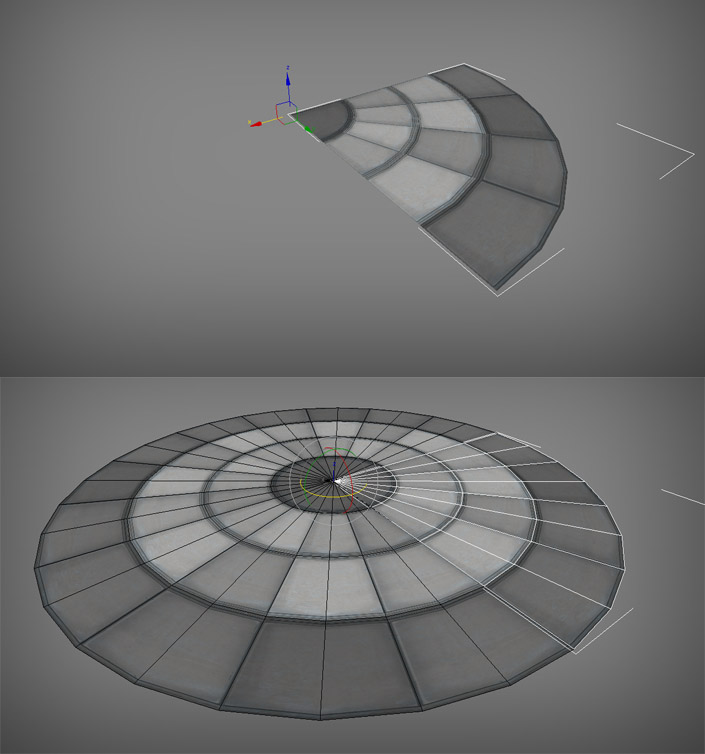
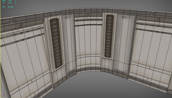
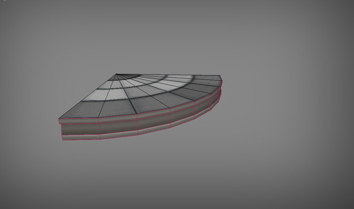
Here's another example, this time from two ceiling pieces. Notice how the trim texture with the grate looks different when mapped on circular geometry:
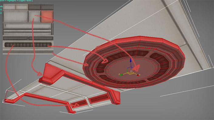
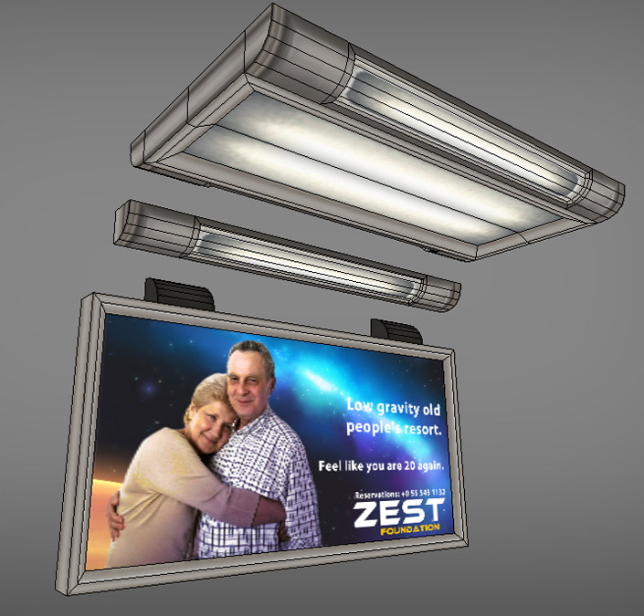
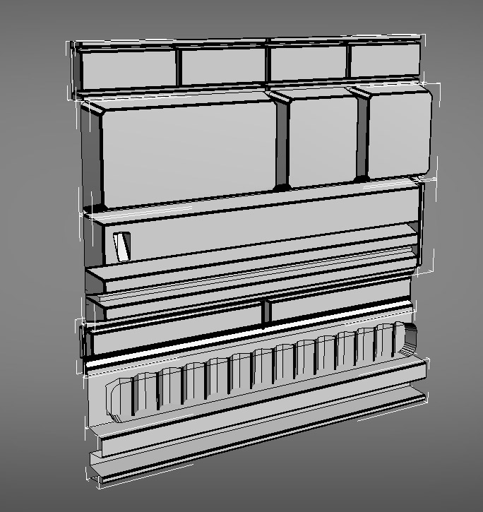
This wall piece was entirely built using the trims collection only. Vertex colors were used to tint some parts:
The trim collection was used even on props. It might be a good idea to use unique textures for stuff like this though.
VERTEX COLORS
Vertex colors were used extensively to tint some parts. This worked really well with my textures since they were so clean and bright. Remember that vertex coloring work just as the "multiply" blend mode in Photoshop so if you have a dark texture or a texture with lots of color variation you won't be able to do much with vertex colors.
Vertex colors work really well in UDK but I found a little bug: They are not picked up by lightmass. I only found this out after I was finished with this environment, so if you are going to tint large areas it might be a good idea to use a colored texture instead.
One of the pieces were vertex coloring was used extensively:

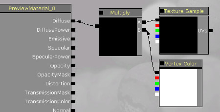
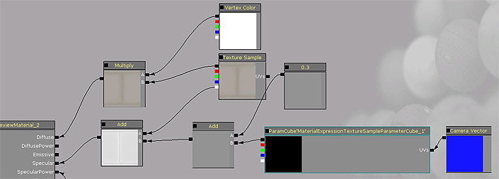
Enabling vertex colors on your UDK material is pretty simple:
Other things you can do with vertex colors:
- Multiply it with the specular map too so you have colored specularity
- Use it as a mask to blend two textures
Tip: You can also the vertex colors using a separate mask. Use a LERP node inside the material editor for that.
CUSTOM CUBEMAPS
Sometimes it's better to use custom generic cubemaps instead of render targets in UDK or other cubemaps sampled from the level itself. I learned that cubemaps sampled from the level work best with glass and similar materials. Metal however benefits a lot from custom cubemaps.
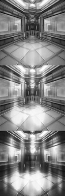
The custom cubemaps I made for Zest Foundation are pretty simple actually. I grabbed an screenshot of the level and modified them heavily. The main idea behind this is to add highlights to the surface instead of actual reflection information.
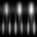
Here's a simple cubemap with just a few highlights:
Another cubemap using a combination of the above cubemap and an screenshot of the level:
Setting up the material in UDK is a bit tricky. First you will need to create the actual CubeMap entity. Do so by right-clicking the content browser and Create New TextureCube. Then set all the faces of the cubemap and save it.
A typical material with cubemapping enabled looks like this (the cubemap mask is saved on the Alpha channel of the "Emissive/CubeMap Mask" texture sample:
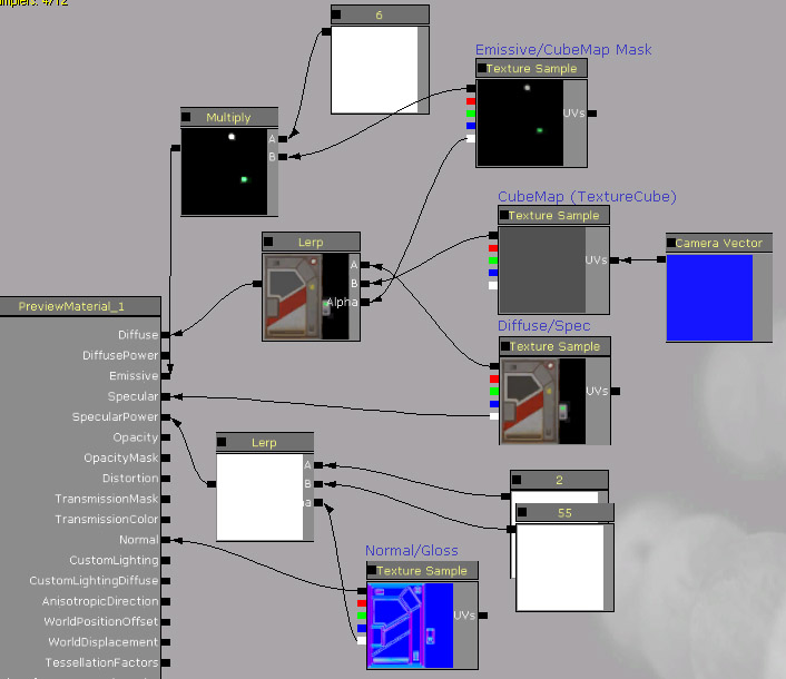
The result:

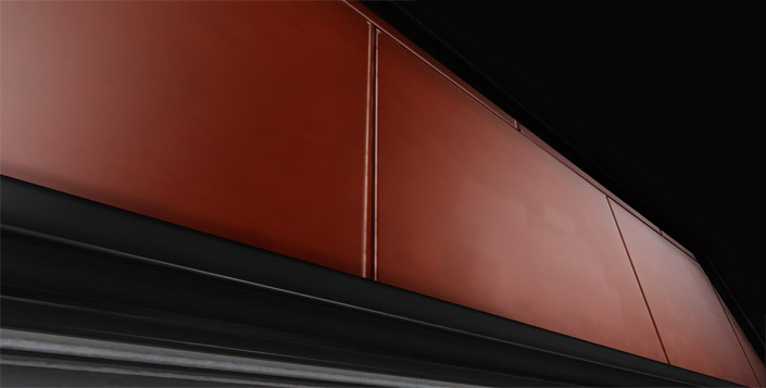
Another example. Here a simple cubemap was added very subtly to the specular map:
The result:
USING THE BEND MODIFIER THE RIGHT WAY
The bend modifier is a very powerful tool in 3ds max but most people don't know how to use it properly. It's not precise and you will end up having to touch up the geometry a bit after use but once you learn this little trick it gets very easy to work with it.
Tip: If you are modeling units for UDK you will need a second UV channel for the lightmap coordinates. Do this before bending your geometry. The bend modifier won't destroy it..
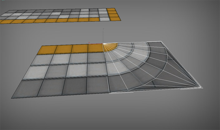
In this example I'll make a 90º curve out of this 1x1 piece (notice the second UV map on the modifier stack):
Add an "Edit Poly" modifier and create vertical loops using connect edges. The more loops the more rounded the piece will be. Try to leave the spacing between the loops consistent on the whole mesh:
Now we are ready to start bending the geometry. I want a pretty short curve, so I added a reference cube that's half the width/length of the 1x1 piece. The extremities of this cube represent the points of contact of the final curved mesh. You can also duplicate the original mesh, rotate 90º and place it on the other extremity of the cube. Make sure the pivot point of the geometry to be curved corresponds to the "starting" point of the curve.
Add the bend modifier. For this piece I had to set the curve to the X axis and a -90 angle. The default settings don't look good though, we'll have to fine tune the bend profile:

To do that, expand the Bend modifier and choose gizmo. The gizmo position controls the bend profile. In this case I had to move it on the X axis until both extremities were close enough:
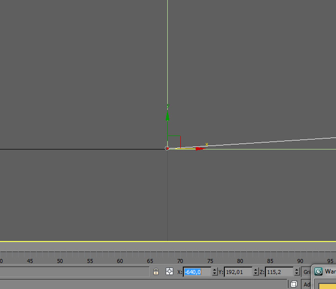
Now comes the ugly part. Go to the Top view and zoom in to get a good view of the ending point of the curve. You will notice that there's a small gap. The trick here is to move the gizmo in small increments using the transform tool at the bottom of the screen. The more you zoom in the more precise the tool gets (make sure to still have the bend gizmo selected).
After that's done, add and edit poly, select the vertexes in the end extremity and check if they are in fact on the grid. Here on this example the end vertexes coordinates are X -639,99. Type in -640 and they should lie perfectly on the grid:
Other pieces built using the same technique:
BAKING TILING TEXTURES
Most of the texture maps used in this environment were baked from simple hipoly objects. The trick is to render these to planes instead of baking to specific geometries. This way you have tiling textures and can reuse them whatever way you want.
One of the Hipoly objects (this one was "exploded" before baking to avoid AO conflicts):
I wrote a tutorial about baking these maps using xNormal, you can read it here.
QUESTIONS AND ANSWERS
Here's a collection of frequently asked questions on forums or via email. Don't hesitate to contact me if you have additional questions.
Q: This may sound dumb, but how do you combine the wall texture and trim texture onto one object. Do you have to dot twp different uv channels? A good example of this is the (Re)Utilizing your textures in a smart way part of your tutorial.
A: You need to use a multi/sub-object material. It's pretty simple. Here's a tutorial about it.
Q: IS EACH TILE ON THE FLOOR A SIMPLE PLANE OR A BEVELED PLANE?
A: They are simple planes mostly. I added a few divisions here and there for vertex color painting though.
Q: ANY CHANCE YOU COULD ADD SOME OF THE PROJECT FILES OF THIS SCENE SO WE CAN REVERSE ENGINEER SOME OF THE WORK?
A: The tutorial covers pretty much everything I've done. If you have specific requests just let me know so I can make additions to the tutorial ;)
Q: TWO QUESTIONS THOUGH YOU TALK ABOUT THE ONE TO ONE RATIO DOES THAT SIMPLY MEAN JUST KEEP EVERYTHING IN A SQUARE BOX? ALSO HOW TO YOU GO ABOUT UNWRAPPING THE LOW POLY DO YOU A) COMBINE EVERYTHING ON ONE SHEET OR DO YOU HAVE INDIVIDUAL TEXTURE SHEETS.
A: What I meant is: Set a base size for all pieces and that will serve as reference for the entire set. If your base piece is 128x128 (1x1), then a 2x1 piece should be 256x128, but never 192x128 for example. If you keep all the entire set relative to the base piece's dimensions you won't have trouble combining them inside the editor. If you have different sizes for each piece then it will be a nightmare to work with them.
As for the low poly I use the textures outlined in the pictures: most of the pieces were built with one tiling texture + another sheet with a bunch of trim textures mashed together.
Q: IF YOU HAVE A SHEET FULL OF TEXTURES YOU HAVE CREATED, YOU THEN GO TO UVUNWRAP, DOES THIS MEAN YOU HAVE TO FIT THE UV COORDS TO THE TEXTURE, RATHER THAN THE OTHER WAY AROUND (DRAW ON THEM)?
A: Yes, that's the idea. You will probably get a little stretching here and there but nobody will notice.
The unwrapping process is pretty straight-forward: Select faces - flatten mapping/planar mapping - map them on specific parts of the trim texture.
The following questions were asked by Jahn Hummel for his graduation thesis:
Q: WHEN DO YOU RECOMMEND USING MODULAR PIECES AND WHEN NON-MODULAR PIECES?
A: Modular pieces work well with pretty much everything but in general you will get better results with non-organic environments, such as sci-fi and urban. But that doesn't mean you can't combine modular elements with unique modeling: When modeling a castle for example, you could models the wall uniquely (always respecting the grid of course) and use modular pieces for archways, stairsets, windows etc... It depends on the kind of results you are aiming for really. Building environments out of small sets of modular pieces is just ways to approach the thing but it's definitely not the only workflow available. A good artist knows when it's best to go for strictly modular sets and unique modeling.
Q: HOW DO YOU DEFINE THE SIZE OF MODULAR PIECES IN AN ENVIRONMENT? WHEREOF DO YOU MAKE IT DEPENDENT?
T: You should always take into account the scale of the environment you are working on and the player scale. If you are working on small tight corridors you can use smaller pieces, but if you are working on a vast open urban environment it might be a good idea to make the pieces pretty big. A good example for this is Crysis 2: The sidewalks are small modules but the buildings' facades are big modules. This is better for performance and facilitates placement in the level.
A good starting point is: If the piece will be visible from upclose it might be a good idea to work with smaller units. If it will be used outside the playable area then it's better to work with bigger modules, merging multiple pieces in the same object.
Q: HOW DO YOU APPROACH SEAMS BETWEEN MESHES?
A: They are unavoidable on lightmap based engines but not much of a problem on dynamic-lighting based ones. To avoid seams you can do one of the following: Add an artificial seam to your piece (such as the extremity of a panel or something like that) or you can merge multiple pieces into bigger ones.
Seams aren't too much of a problem when the environment is fully textured and lit though, so you shouldn't worry about this unless they very very noticeable.
Q: WOULD YOU RECOMMEND USING POWER-OF-TWO UNITS TO BUILD MODULAR PIECES WHEN USING AN ENGINE THAT WORKS WITH A METER-BASED SYSTEM (INSTEAD OF A GENERIC UNIT ONE)?
A: Depending on the scale of the player model it's possible but it's definitely not a rule set in stone. If you convert power-of-two "generic units" to meters you still get pretty reasonable values: 256 units could become 2,56mts so yeah, it's possible.
Q: DID YOU USE A TEXTURE ATLAS FOR YOUR TEXTURES IN ZEST FOUNDATION? WHEN DO YOU USE TEXTURE ATLASES?
A: I did actually, for the trims sheet. I hardly ever use texture atlases though. It's hard to plan them in advance and it's definitely harder to adjust the UVs later on if you decide to starting using them down the road.
Q: DO YOU CREATE YOUR OWN MIP-MAPS?
A: I never had to but I know you can create some cool effects editing the mip-maps. For example, if you are working on a large tiling texture for a terrain you could blurry the mip steps a little to avoid obvious texture repetition. I know they did this on Far Cry 2.
Q: WHAT WOULD YOU DO DIFFERENTLY WERE YOU TO MAKE THE ZEST FOUNDATION ENVIRONMENT AGAIN?
A: The lighting. I'd have used the sun light better, it's barely noticeable with all the interior lights placed in the level. I found it very hard to find a balance regarding this because of how lightmapping works in UDK: Tweak a light's value a little and the result will be pretty different.
Q: HOW DO YOU THINK MODULARITY WILL BE USED IN THE MAKING OF ENVIRONMENTS IN THE FUTURE? DO YOU THINK IT WILL CHANGE? WHY/WHY NOT?
A: Well, modularity has been around since the very fist videogames if you think about it. Back in the days entire games were constructed out of sets of 2D tiles with fixed proportions, so yeah, unless a new revolutionary workflow appears we will keep using modularity for a very good time.
I like to think that the 3D modules I create now are in fact an evolution of the 2D textures I used to make back in the Half-Life 1 days. The difference is, instead of working on a flat 2D plane I now have an extra axis but the idea is pretty much the same.